 |
 |
 |
 |
 |
 |
 |
 |
 |
 |
 |
 |
 |
 |
![]()
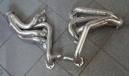 |
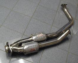
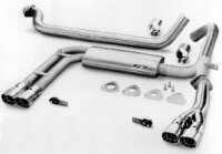
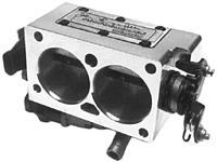
Arizona Speed and Marine ceramic coated headers for '94-95 f-body. These headers don't fit up to the stock y-pipe, but are a better configuration than the '96-7 style headers for dual-cat cars. Configured with a dual-cat y-pipe, I think they're the next best thing to longtube headers. These have 1 3/4" primary tubes, into 2 1/2" collectors. These were installed with SCE copper head gaskets, Stage 8 locking bolts, and "copper" gasket seal. Random Technology stainless steel dual-cat y-pipe for '94-95 f-body, completes the package, providing the emissions-required two catalytic converters, and a clean fit to the AS&M headers. This pipe consists of two 2 1/5" tubes, high-flow catalytic converters, and a 3" outlet. It doesn't line up to the standard cat-back, unfortunately, and requires some customization at that end. Installation: See the install page, for specifics. |
 |
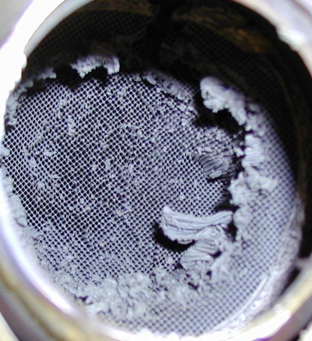
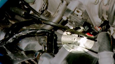
Soon after installing the new Random Tech y-pipe, I blew out a catalytic converter while road racing. Click on the picture to see a nice close view, it's pretty cool. Anyway, glowing embers of the cat were shooting out the tailpipes, it was quite exciting. The car was running rich at the time, possibly because there was a leak in the O2 sensor bung (weld from Random). This has been fixed now, but I haven't tested everything yet.
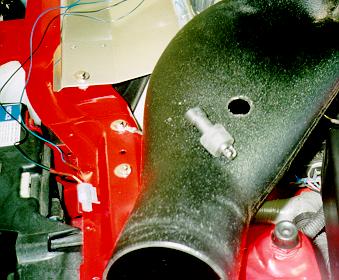
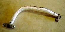 I wrapped the EGR pipe with heat-resistant asbestos tape, to help keep
the intake manifold cool. This pipe pulls exhaust gasses back into the intake manifold, as
part of the smog system, and it's heat is sometimes blamed for melting the manifold gasket
and causing the dreaded "intake manifold oil leak."
I wrapped the EGR pipe with heat-resistant asbestos tape, to help keep
the intake manifold cool. This pipe pulls exhaust gasses back into the intake manifold, as
part of the smog system, and it's heat is sometimes blamed for melting the manifold gasket
and causing the dreaded "intake manifold oil leak."
I also blocked off this exhaust return by inserting a plate between the pipe and the intake manifold. This will cause an EGR SES code to set on the 1996+ computers (OBD-II), so I put it back to stock pretty soon after this experiment. The SES light will come on when cruising on the freeway in 6th gear, since that's when EGR is activated. It's no big deal, but leaving the SES light on all the time isn't something I want to do.
Installation: The top end of the pipe bolts into the intake manifold at the top right side, with two 13mm nuts (use a small socket wrench to remove them) and a gasket. The bottom fits into the passenger's side exhaust manifold or header with a single 13mm nut. To do the block-off only, you don't need to remove the bottom end of the pipe. Just remove the top, and cut a piece of aluminum that's the same size as the gasket, but without the hole in the middle. Slip that between the pipe and the manifold, then re-attach the pipe. If you're really anal about it, use a piece of heat-resistant tape, sandwiched between two aluminum pieces. You want to keep heat away from that manifold.
|
Borla street/strip cat-back exhaust system, part 14555. This exhaust system is made of 3" diameter T-304 stainless steel, and incorporates a nice tuning feature: it has a set of block-off plates which can redirect exhaust either through the muffler (nice and quiet), all the way to completely circumventing it (nice and loud). It takes just a few minutes to swap the plates. I was using the 1.75" plate with the 350 engine, but now I've opened it up all the way. This is a fantastic mod, both from a power perspective and from the sound! It did add an slight vibration at 3000 RPM, that couldn't be eliminated, until I installed the LPE engine (that's an expensive fix!). It was diagnosed as a harmonic thing in the Y pipe. Installation: I had the Borla installed
at my local Midas, and it fit just fine. I made the usual adjustments of adding a couple
washers under the cross-brace (lowering it about ¼") and raising the tailpipes up to
clear the Panhard rod. These seem to be typically required to avoid rattling. |
")
 After the engine installation, my Borla started
rattling all over again, since it was removed as well. This exhaust has always rattled a
bit, and I have spent quite a bit of time adjusting it up and down, and lowering that
cross-brace (which has been hitting speed bumps as a result). I decided to fix this once
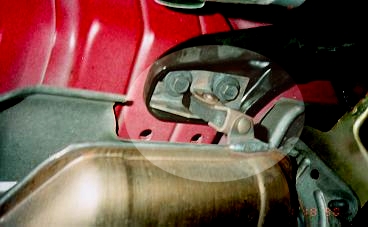
and for all. I took the car back down to Midas and had them fabricate a hanger, which
holds the front of the exhaust, by the passenger cat (in my 2-cat car) up about 3/4".
This hanger augments the bracket that is attached to the tranny, because that bracket sags
and lets the exhaust drop down on bumps. The bracket is welded to the cat, and bolts onto
two bolts right above it. It is insulated, so this isn't a "weld the exhaust to the
body" fix. I was able to remove all the washers from my cross-brace, and have NO
exhaust rattles. Also, since that cat is the low point on the car, I've now raised up the
clearance by quite a bit, and don't hit anywhere near as many speed bumps or driveways as
before.
After the engine installation, my Borla started
rattling all over again, since it was removed as well. This exhaust has always rattled a
bit, and I have spent quite a bit of time adjusting it up and down, and lowering that
cross-brace (which has been hitting speed bumps as a result). I decided to fix this once
and for all. I took the car back down to Midas and had them fabricate a hanger, which
holds the front of the exhaust, by the passenger cat (in my 2-cat car) up about 3/4".
This hanger augments the bracket that is attached to the tranny, because that bracket sags
and lets the exhaust drop down on bumps. The bracket is welded to the cat, and bolts onto
two bolts right above it. It is insulated, so this isn't a "weld the exhaust to the
body" fix. I was able to remove all the washers from my cross-brace, and have NO
exhaust rattles. Also, since that cat is the low point on the car, I've now raised up the
clearance by quite a bit, and don't hit anywhere near as many speed bumps or driveways as
before.
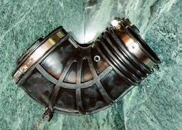
K&N Filtercharger Injection Package Kit (FIPK), part 57-3010. This replaces the stock intake, and pulls much more air in to the engine. See it installed, in the engine bay photo.
Installation: Installing this was a bit of a bear - maybe it was just me (my first mod!). Pulling the stock intake was surprisingly difficult, since the parts are all flexible rubber. I had to get a friend over so we could each yank on opposite ends. After that worked, the rest of the install was simple, until it came to attaching the large air filter. This goes on from underneath, and requires an essentially blind attachment of a band clamp.
Moved the Intake Air Temperature (IAT) sensor down from the intake elbow to the base of the K&N FIPK. This allows the PCM to read cooler air, running richer, and pulling in the timing.
Installation: I did this by finding a rubber
plug, and drilling a ½" hole in it for the sensor. Then, I drilled a larger hole in
the FIPK to fit the plug. The IAT wires were lengthened to reach to the new location.
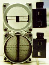
Replaced my Mass Air Flow (MAF) Sensor with MTI's ported and calibrated version. On the left, you see the stock MAF below, and the ported one above. The screen and central blade are removed, the diameter is bored to 73mm, and the resistors are recalibrated. I felt that with the big engine, the stock MAF might be a block in the intake.
Installation: Simple to install, just slip the old one out and the new one in. There are no computer changes, other than the natural learning it will do as more air comes in. MTI claims 8-10 horsepower increase, though I haven't dyno'ed this mod.
At the track, I appear to have gained at least 1 mph, and ran my
best time as soon as I put this on, 0.18sec faster than my previous. I don't know
that I'd give the whole gain to this MAF, but it does appear to have helped.
Just for grins, I installed the 1LE intake elbow, and eliminated the stock silencer.
From the factory, the throttle body has coolant running though it. This coolant is intended to warm the incoming air flow, to prevent icing during cold temperatures. Unfortunately, this is only relevant at freezing temperatures, and at all other times it only serves to warm the air, which is not good for performance. The coolant can be routed around the throttle body, rather than through it, for gains of about 6hp and 7ft-lbs (see Keith's WS6.COM dyno page for lots of useful dyno results like this).
The coolant enters the throttle body from the passenger side through a steel line heading rearward along the valve cover. It joins into a short hose with a 90° turn in it, which then connects to the lowest of three hoses on the TB on that side. The coolant flows through the throttle body, and exits on the driver's side, down low. This hose goes straight to the radiator, right at the fill neck. The idea, then, is to remove both of these hoses from the throttle body, and connect them together such that the coolant will flow directly from the steel line to the radiator.
 Installation ('95-7 only, other f-bodies
are slightly different): Drain a couple quarts of coolant out of the
radiator first, from the bottom passenger's side of the radiator. The driver's side hose comes off pretty easily. The passenger's side
requires a lot of pulling. To make things easier, remove the "V" shaped
alternator bracket, and any hoses and electrical connectors in the way. Slide the hose
clamps toward the center of the hose, off the pipe, and spray the hose with WD-40. Then,
lots of pulling and tugging is necessary. I ended up leaving the stock hose connected to
the steel line, and getting a 1½" piece of 3/8" aluminum pipe, and joining both
stock hoses to this pipe (see picture). The radiator hose can be rerouted a bit more
conveniently than the stock routing. Plug the ends of the two connections to the TB with
5/16" plastic plugs, if you want to keep dust out of there. Remember to bleed the
coolant lines (the two brass screws) after you refill the coolant.
Installation ('95-7 only, other f-bodies
are slightly different): Drain a couple quarts of coolant out of the
radiator first, from the bottom passenger's side of the radiator. The driver's side hose comes off pretty easily. The passenger's side
requires a lot of pulling. To make things easier, remove the "V" shaped
alternator bracket, and any hoses and electrical connectors in the way. Slide the hose
clamps toward the center of the hose, off the pipe, and spray the hose with WD-40. Then,
lots of pulling and tugging is necessary. I ended up leaving the stock hose connected to
the steel line, and getting a 1½" piece of 3/8" aluminum pipe, and joining both
stock hoses to this pipe (see picture). The radiator hose can be rerouted a bit more
conveniently than the stock routing. Plug the ends of the two connections to the TB with
5/16" plastic plugs, if you want to keep dust out of there. Remember to bleed the
coolant lines (the two brass screws) after you refill the coolant.
|
Copyright © 1997-2004 David Mills, no part of this site (http://www.go-fast.org/) may be reproduced without permission of the author. The author makes no claims or guarantees as to the quality of the information on this site. I'm an enthusiast just like you, and while everything here is correct as I know it, I'm not responsible if your car breaks. |