 |
 |
 |
 |
 |
 |
 |
 |
 |
 |
 |
 |
 |
 |
![]()
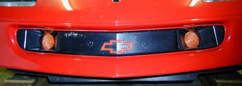
Version 1
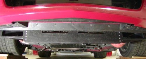
Version 2
Routing brake ducts on a 4th Generation F-Body isn't the easiest task in the world. Space is limited, and it's a fairly daunting task. Jon A's setup was the first I saw that really made me think this was possible on a street-driven car, and that the ducts might withstand the rigors of just driving around town. So thanks, Jon! This system is similar to his, but I chose to place the duct entry in the fog light openings. I wanted to put them in the fog light openings mostly because I felt that there was already a lot of air pressure right there, that would help force air into the ducting. Since I never use my fog lights anyway, this let me feel like I didn't change the aerodynamics of the car at all, yet got some use out of that pressure zone.
Subsequent to the version in the fog light openings, I had an incident at the track that required a new nose. Rather than go to all the trouble again, I re-positioned the intake into the sides of the air dam, as seen in the "version 2" picture above. Frankly this worked just as well, and was certainly easier to do! Most of the install is identical in both setups.
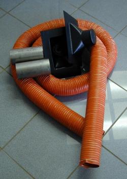
Parts
You'll need: 11' of orange silicone duct (from Racer Parts Wholesale). I used 3" duct, but 2 1/2" duct would be easier, and I've heard of running radiator hose (two lines per side) as an easier, more permanent setup. Two ABS inlet ducts (NACA ducts, again from RPW). Two short stainless pipes, about 4" long each, and the diameter of your hose (I got these from a local exhaust shop, they don't have to be stainless of course). From your local hardware store, get two u-bolts, diameter is about half an inch less than the stainless pipe; two stainless hose clamps to hold the hose onto the stainless pipe, zip ties; four push-in clips to hold the ducts in position in the fog light openings; and three replacement push-in clips to re-attach the bottom of the nose.
Tools
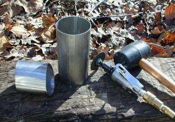
Die grinder with a cutting blade, and a bench grinder,
to cut and smooth off the stainless pipes
Dremel and files to cut the plastic in the fog light openings, and to trim
the inlet ducts to shape
Glue to attach the hose to the inlet ducts
Willingness to do some hacking on various body panels is critical.
 |
|
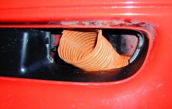
Cutting the Opening
The toughest part of the project (time-wise, and mental stress-wise) is installing the ducts into the fog light openings. The ducts must be cut to shape, and you'll need to cut some material out of the fog light opening, to make room. Of course this is for the 'version 1' solution. Version 2 is much simpler, and is simply a matter of cutting the holes in the air dam and pop-riveting the ducts to the back. . So here goes...
 First,
remove the fog lights themselves, and the bracketry that holds them in
place. Since you'll need to get behind the nose, you might as well pull
the three clips that hold the lower section of the nose up behind the fog
lights, at this point. You should then have a nice opening, but you'll see
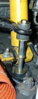
that the frame is fairly close to where you'll want to run the duct. Yes,
this is a flaw in my setup, since the air is expected to take a fairly
sharp turn to get under the frame. One thing that will help is to cut some
material out of the upper and lower portions of the fog light opening. to
add some clearance for the hose. I cut about 1/2" from the top, and
1" from the bottom portion of the opening. Push the hose in from the
rear, as in the picture at the right, and get a fell for how much of a
bend you'll need. Less bend will give you better flow, of course.
First,
remove the fog lights themselves, and the bracketry that holds them in
place. Since you'll need to get behind the nose, you might as well pull
the three clips that hold the lower section of the nose up behind the fog
lights, at this point. You should then have a nice opening, but you'll see
that the frame is fairly close to where you'll want to run the duct. Yes,
this is a flaw in my setup, since the air is expected to take a fairly
sharp turn to get under the frame. One thing that will help is to cut some
material out of the upper and lower portions of the fog light opening. to
add some clearance for the hose. I cut about 1/2" from the top, and
1" from the bottom portion of the opening. Push the hose in from the
rear, as in the picture at the right, and get a fell for how much of a
bend you'll need. Less bend will give you better flow, of course.
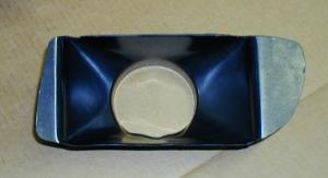 Next,
you'll want to shape the duct such that it fits into the opening. I first
cut the rear section (the part you connect the hose to) such that it's
only about 1/2" long, and then trimmed the surrounding area of the
duct, little-by-little, until it fit in nicely. You can see the final
result at the left.
Next,
you'll want to shape the duct such that it fits into the opening. I first
cut the rear section (the part you connect the hose to) such that it's
only about 1/2" long, and then trimmed the surrounding area of the
duct, little-by-little, until it fit in nicely. You can see the final
result at the left.
At this point, I glued
the hose to the back of the duct with some serious wet/dry glue, and ran a
bead of hot-glue around the outside as well.
|
|
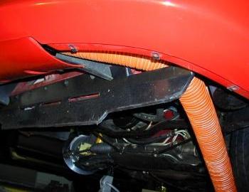
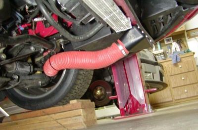
Here's the hose, running in the general path it'll be taking when the other end is connected. |
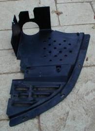
You'll also need to cut holes in the two covers under the fenders, as shown on the right. This will allow the hose to route nicely through, and come out just at the inner corner of the fenderwell, where the swaybar is. |
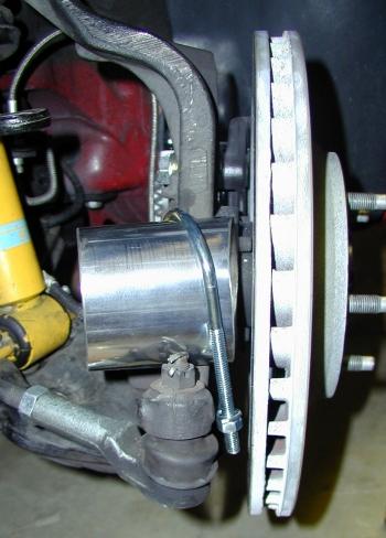 At
the rotor, you want to duct the air as much as possible directly into the
center of the rotor, so that it will blow in-between the rotor faces, in
the existing cooling vanes. To do this, the stainless pipe should be cut
and shaped so that it sits on the spindle, in the notch where the tie-rod
connects. You can see this in the picture at left. I pounded the pipe into
an oval, as well as cutting each end at an angle to match how it will
align against the rotor. This takes a bit of trial and error, cutting off
a section at a time until it seems right. Bolt the pipe down with the
u-bolt, swing your spindle left and right to see how it clears your
swaybar, mark it, cut it a bit, etc. You'll get it, just take it slowly.
At
the rotor, you want to duct the air as much as possible directly into the
center of the rotor, so that it will blow in-between the rotor faces, in
the existing cooling vanes. To do this, the stainless pipe should be cut
and shaped so that it sits on the spindle, in the notch where the tie-rod
connects. You can see this in the picture at left. I pounded the pipe into
an oval, as well as cutting each end at an angle to match how it will
align against the rotor. This takes a bit of trial and error, cutting off
a section at a time until it seems right. Bolt the pipe down with the
u-bolt, swing your spindle left and right to see how it clears your
swaybar, mark it, cut it a bit, etc. You'll get it, just take it slowly.
'Version 1' and 'version 2' ducts are
identical at the rotor end.
 |
|
By the way, I gained quite a bit of clearance by lengthening my endlink spacers up to 2 1/2". You might want to do this too.
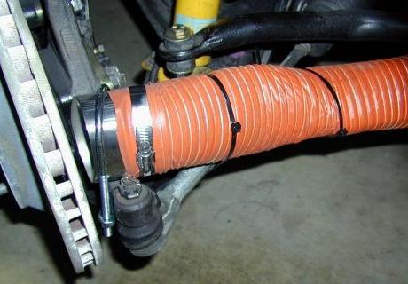
Once
you think the pipe has been cut to the right shape and length, slide the
duct hose on, and clamp it down. you'll be using zip-ties to connect the
hose to the tie rod, as shown on the right. Leave enough slack in the hose
so that it will reach both steering extremes. Then you may need to squeeze
the hose a bit here and there, to shape it such that it clears the swaybar
during movement.
Conclusions
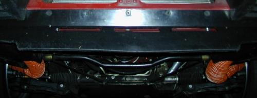
Finished version 1 product, as seen from underneath.
Finished version 2 product from underneath
These are tucked up nicely, and don't cause any ground clearance issues. The collisions though are with the ducting against the wheels and swaybars. You need to keep an eye on them and try to zip-tie the hose out of the way as much as possible, and it will probably need to be replaced once in a while. On the track, there is a noticeable cooling improvement, with both setups.
|
Copyright © 1997-2004 David Mills, no part of this site (http://www.go-fast.org/) may be reproduced without permission of the author. The author makes no claims or guarantees as to the quality of the information on this site. I'm an enthusiast just like you, and while everything here is correct as I know it, I'm not responsible if your car breaks. |